Your Mission
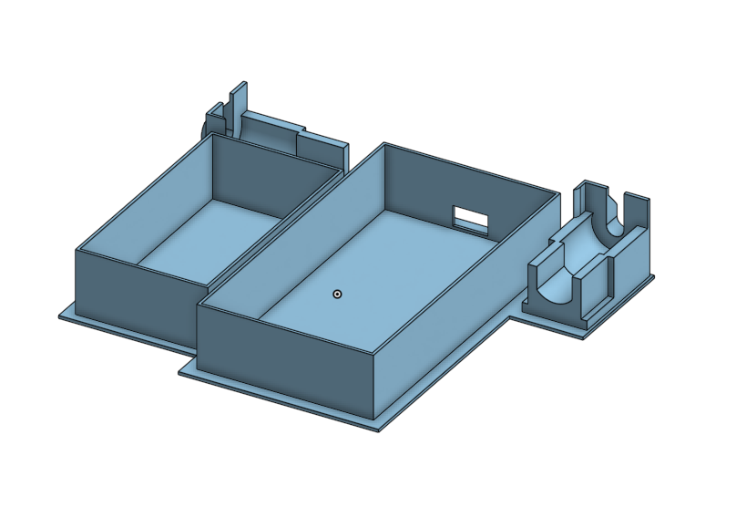
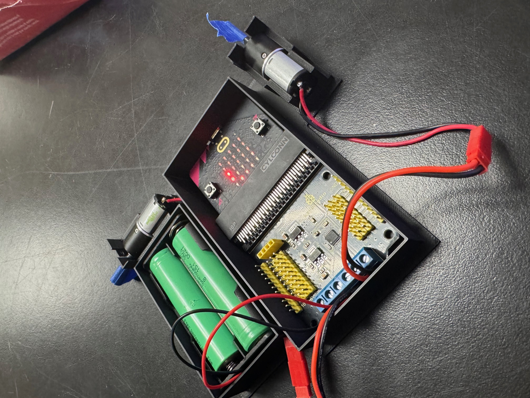
Build a sturdy RC car base in Onshape that holds your motors, Micro:bit V2 + Keyestudio DRV8833 Motor Driver HAT, and battery pack. Follow each step and match the icons so you always know whether to 🎯 select, 🖱️ click, or ✋ drag.
What This Base Holds
Class Kit Electronics
- Microcontroller: BBC Micro:bit V2 with on-board speaker, microphone, and 5×5 LED grid.
- Motor driver: Keyestudio DRV8833 Motor Driver HAT (P13–P16 handle the dual DC motors, supports a 3–10 V motor supply at roughly 600 mA continuous per channel).
- Power: Separate power for the Micro:bit and the motors. Feed the HAT through its screw terminal, then use the slide switch to cut motor power when wiring.
- Layout tips: Reserve room for the battery tray and give the rear wheels clearance so the motor wires can route without rubbing.
The model leaves space around the edge connector so the HAT can plug in cleanly while keeping the JST battery lead accessible.
⭐ Before You Start: Mouse vs. Trackpad
In Onshape, 🖱️ click means tap and release, while ✋ drag means move the cursor without holding any buttons. Try these gestures in a blank document first.
Trackpad users
Use two fingers to orbit the view and pinch to zoom. Hold Shift while dragging to pan.
Mouse users
Right-click drag to orbit, middle mouse (scroll wheel) drag to pan, scroll to zoom.
Part 1 — Create the 6×6 Base Plate
- Open a new document. Go to Onshape → 🖱️ click Create Document → name it RC Car Base – YourName.
- Start a Sketch. In the Feature Tree, 🎯 select Top Plane → choose ✏️ Sketch. Your view tilts flat.
-
Draw a 6×6 square. Pick the Rectangle Tool,
🖱️ click to start, ✋ drag,
click again, type
6 infor width and height, press Enter. Green tip: Dimensions lock the size no matter where the rectangle sits. -
Extrude the plate. Finish Sketch → choose Extrude
🖱️ → select your square → distance
1 mm→ OK.
Part 2 — Build the Assembly
- Create an Assembly: at the bottom tabs, 🖱️ click the + → Create Assembly.
- Insert your 6×6 part: 🖱️ click Insert → select the part → OK. It appears as a ghost part.
- Insert motor mounts: click Insert again → browse your STEM shared document → double click the Motor Mount to add two copies. Add a simple block for the Keyestudio driver so you can check cable clearance.
Part 3 — Fix the Base & Attach Motors
- Fix the base. 🎯 select the plate → right-click → Fix. It turns green and stays put.
- Planar Mate. Choose Planar Mate → select the bottom face of the motor mount → select the top face of the base → repeat for the second motor.
- Fine alignment. To rotate, click the circular handle then drag. To slide, click the arrow then drag. Green tip: click, release, move = preview. Drag = move. Leave space for the motor wires to exit next to the driver HAT.
Part 4 — Edit In Context
Remember: Part Studio is for building parts. Assembly is for connecting them. Editing in context lets you sketch walls while seeing the motors.
- Right-click the plate in the Assembly → Edit in context.
- You pop back to the Part Studio with translucent motor mount references.
- Green tip: The assembly tab icon gains a tiny pencil so you know you are editing in context.
Part 5 — Sketch & Extrude the Walls
- Start a new sketch on the top face of the plate. Use the Line Tool or press L to outline where the walls should go. Make sure the sketch loops are closed.
-
Thicken the walls with the Offset tool. Select each segment → choose Offset → distance
1 mm. - Finish sketch → Extrude the wall profiles upward about
1 in.
Need a deeper dive? The Onshape Offset sketch tool help page covers keyboard shortcuts and troubleshooting tips (opens in a new tab).
Part 6 — Finish Up
- Return to the Assembly. Your walls appear in place.
- Adjust motor mounts if needed so wheels clear the walls.
- Add extra features: holes for zip ties, name plates, protective bumpers.
🎉 You did it!
Export your assembly and get ready for 3D printing or laser cutting.